向下滚动
🌠 游戏说明
深入了解游戏世界
体验前所未有的游戏乐趣
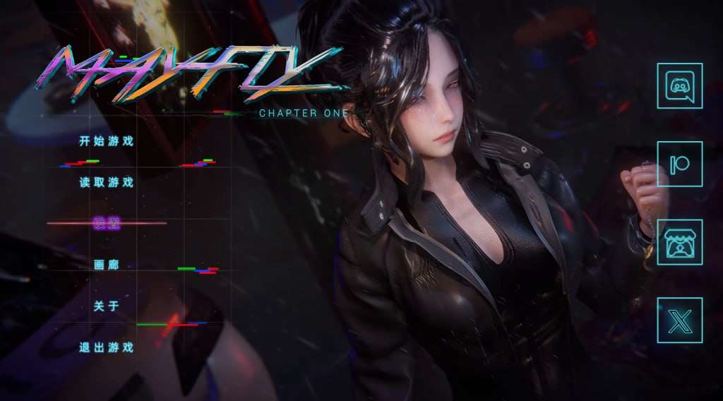
蜉蝣|MayFly。专业的游戏平台,为您提供优质的游戏体验。
动作战斗
流畅的战斗系统,爽快的打击感
开放世界
广阔的游戏世界等你探索
多人协作
与朋友一起冒险,共同成长
成就系统
丰富的成就和奖励等你收集
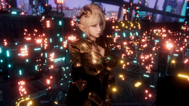
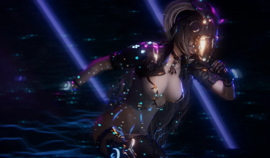
游戏截图


游戏信息
类型
动作冒险
平台
PC/Mobile
语言
中文
大小
2.5GB
💉 使用攻略
掌握游戏技巧
成为游戏高手的秘诀
蜉蝣主站记录背景设定在德文郡,这座庞大的超级都市呈现出明显的社会阶层分化,被划分为上下二个截然不同的区域。上层区域环境优雅,高楼耸立,是富商巨贾和社会精英的居住地;而下层区域则人口密集,生活着普通劳动者和各种社团组织(包括传统的神奇团体)。
数个年前,1场神奇事件导致城市中的部分居民(特别是年轻群体)突然接收了超越常人的特殊能力。然而,这些异能者中的1些人发起利用自身能力从事违法行为,特别是针对上层区域的富裕阶层。这种现象引发了社会秩序的动荡,治安形势日益严峻。
为了应对日益严重的混乱局面,都市管理当局制定了二项特殊法规:《特别执法条例》和《异能者管理法》。前者授权特定的异能者执行更广泛的执法职责;后者则对异能者建立了专门的管理体系,包括设立专门的矫正机构。
在这样的天地背景下,你将扮演1名拥有特殊异能的执法者,你的各个唯1抉择都可能影响你与他人的关系和整个城市的命运走向。是像蜉蝣1样短暂地存在于这座表面繁华的都市中,还是在混乱中开辟出1条独特的道路,留下永恒的传说?"改变命运的力量就在你手中。"
沉浸于精美的感受画面,感受高级建模与动态效果带来的视觉盛宴。EP2重置版带来了显著提升的渲染质量、添加的体积光/体积雾以及更精细的主角模型,各个1帧都经过精心打磨。
高速下载
开始你的冒险之旅
免费下载,即刻体验
2.3M+
总下载量
4.9/5
用户评分
900K+
活跃玩家
安全下载
高速安装
完全免费
24/7支持
系统要求
Windows 10+
8GB RAM
GTX 1060
50GB 存储