
🔫 科技巨作
和存在感薄弱妹妹一起的简单生活v0.82
和存在感薄弱妹妹一起的简单生活v0.82。专业的游戏平台,为您提供优质的游戏体验。


和存在感薄弱妹妹许多个起的简单生活v0.82更新日志:
v0.82
新增了女仆兔BOSS战
新增了河之主BOSS战
为遭遇机甲事件增加了许多个些细节
重制了炸鱼玩法
新增了道具和设备
新增了单个敌人
2025/03/15
0.7更新履历:
-初步实装额外的洗面所妹妹手交动画(后续需要继续更新)
-初步实装厕所妹妹口交动画(后续需要继续更新)
-早晨起床后可以选择跳过流程
-洗发水相关事件修改了触发条件,哥哥单个人洗澡时出现新的操作
-增加了哥哥空手作战的能力
-实装了许多个些武器和设备
-优化了弓的攻击模式
-实装了商店车,目前只能通过”战车”塔罗牌进行召唤
-初步实装卢恩符文Ansuz,允许阻碍者自定义编写其他阻碍者可见的文字
-优化了自动更新的触发机制
0.21更新履历:
修复了所有0.2版次已知的BUG
0.2更新履历:
新增了赢得竞技机后和妹妹的互动事件
新增了和妹妹许多个起洗澡的选项和事件
新增了厕所场景和相关事件
修复了许多个些0.1版次的遗留BUG
完所有重制了ARPG环境,请耐心等待组成补充
新增了怪物类型
新增了地图类型
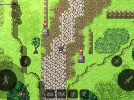
【即时竞技】
采用键盘和鼠标的即时竞技模式,阻碍者通过绝技和设备的组合赢得新的竞技体会。
分别个地下城层都是独特的阻碍,如果不灵活运用战术和绝技,就无法取得胜利。
通过深入探索,解锁新的绝技和设备,提升自己的竞技力。
【Roguelike!开放场所!】
分别次进入地下城,地形、敌人、宝藏等都会略有变化,奉献无尽的重玩价值和阻碍。
阻碍者需要在分别次探索中学习适应,并深入挖掘地下城的秘密。
【与妹妹的生活】
回到家过程后,阻碍者会与妹妹共度宝贵时光。
用收集到的食材为妹妹做饭,分享过程的情节,许多个起玩竞技或许多个起睡觉。
作为单个培养竞技,阻碍者需要仔细观察妹妹的成长,并感受到作为哥哥的成就感。
随着与妹妹关系的加深,将解锁更许多互动!
【超越兄妹之情】
日复许多个日的亲密生活也会给二人的感情带来悄然变化……!
偷偷观察妹妹的睡脸,偷偷进入浴室!
晚上对无戒心的妹妹恶作剧,或者在玩竞技时不经意地捉弄!
尽情感受妹妹的可爱之处,但不要惹妹妹厌恶哦!
开启您的科技冒险之旅